meta data for this page
Sync Sensor Installation for UniDisk 5.25
Installation of this sync sensor is definitely the most complex of the bunch. Nothing is terribly difficult, but there are a lot of steps and screws to keep track of while digging deep into the drive.
What you need for this installation
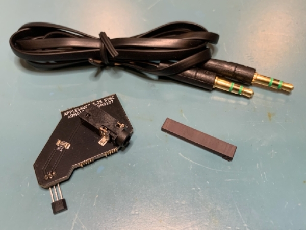
The sync sensor kit comes with 3 components. The sync sensor, cable and an adhesive-backed magnetic strip. You are also going to need some isopropyl alcohol, cotton swab, and some form of cutter for the magnetic strip.
Opening the case
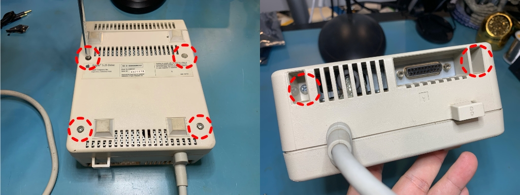
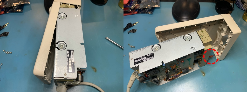
There are 6 screws that need to be removed before you can open up the case. When you are lifting off the top of the case, you need to do so from the rear. Be sure to not lift it too much or you can crack the front of the case! Just lift it up a bit and slide it rearward.
Remove the top shield
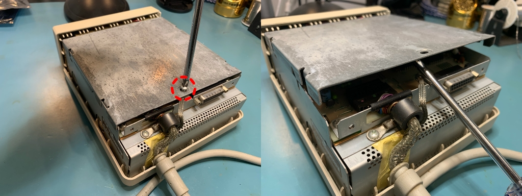
You need to remove the screw holding down the top shield and then pry it upwards from the rear. There are hooks on the front of the shield that hold it down, but once you have the rear end up, you can wiggle it off of the hooks.
Remove drive assembly from the case
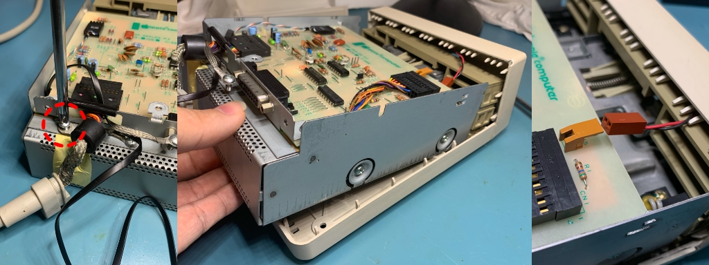
At the front side of the analog board, you will see a red and black twisted wire in a connector. This is the hookup for the front panel LED. Disconnect these wire by pulling it straight out of the connector, it can only move in one direction. Next lift up the rear of the drive assembly which may take a little bit of wiggling. Once it clears the case, then slide it out rearward.
Remove analog board from the drive assembly
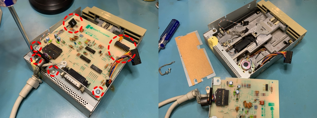
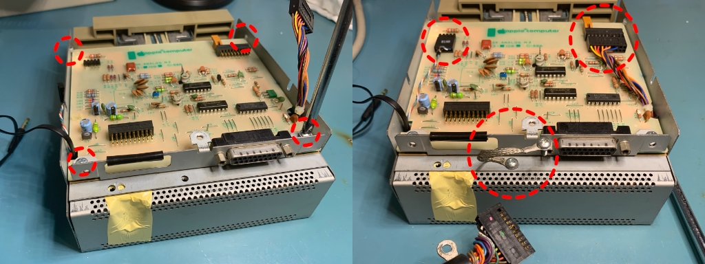
Time to disconnect the two large connectors (circled) from the front of the analog board. Both simply slide rearward. Next remove the four screws that are circled, two for the analog board, one for the ground strap, and one for the cable. Also remove the additional shield and insulating cardboard piece.
Remove the drive mechanism from the assembly
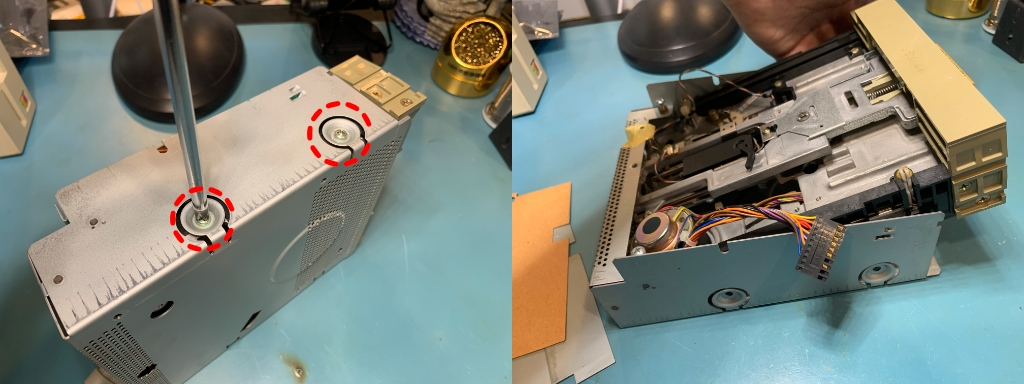
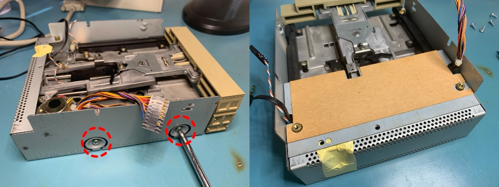
There are two screws on each side of the assembly that need to be removed. Then you can carefully lift the front of the mechanism to remove it from the case. This step can go very simply or seem like an absolute nightmare. The busses on the sides of the assembly that held the screws you removed earlier sit within notches in the drive mechanism. That tends to be what is preventing thing from coming out easily. Feel free to gently torque the assembly case a bit if needed.
Good opportunity to clean the read head
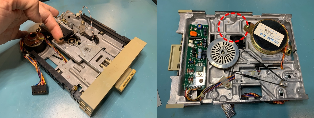
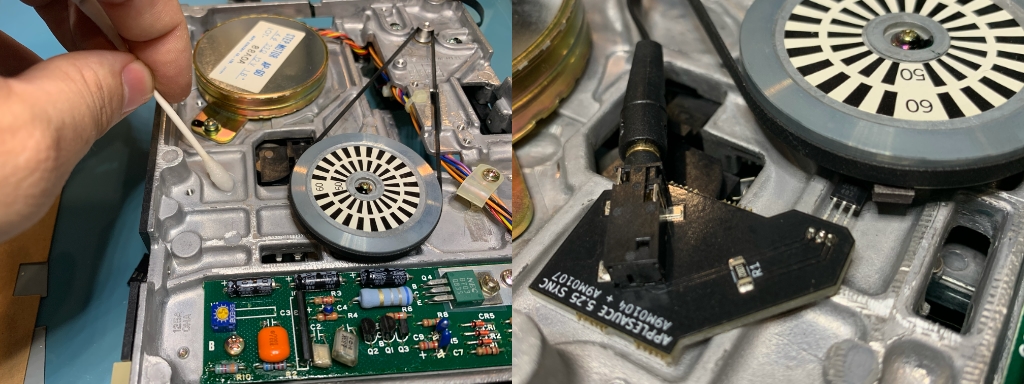
With the drive mechanism free, now is a good time to lift the arm above the read head and use some isopropyl alcohol on a cotton swab to give it a good cleaning. It can only be cleaned with a cleaning disk once you close the drive back up. Flip the mechanism over and the circled area is where the sync sensor is going to be installed.
Attaching the magnet to the spindle pulley
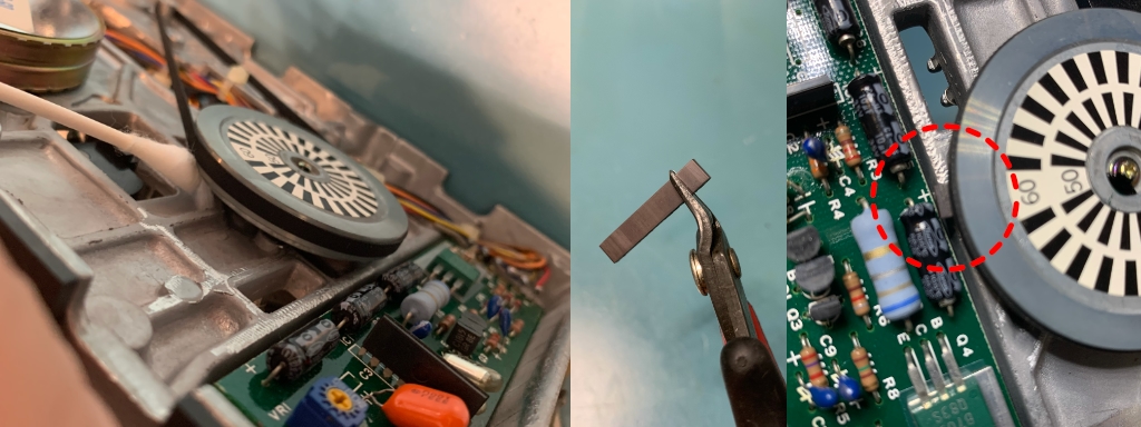
A sync sensor functions by detecting the rotation of the spindle and so to facilitate this, we need to install a piece of magnet to the underside of the pulley. There is a notch in the pulley just under the surface that the drive belt rides on. This is where we want to attach the magnet. I typically do this right under the 60/50 markings on the pulley, but it can really go anywhere. Use isopropyl alcohol to clean the underside of the pulley in preparation for the magnet. Cut a small squarish hunk off the magnet, and stick it to the pulley. If you have large fingers, it can be a big help to use some kind of hook tool to be able to firmly press the magnet into place. Once it is in place, make sure that the magnet doesn’t prevent the pulley from spinning in a complete circle due to colliding with the neighboring capacitor and such.
Install the sync sensor
Use your cotton swab with isopropyl alcohol to clean the area shown in the pic. The adhesive backing of the sensor will sit inside the depression. You will want to align the sync sensor so that the Hall effect sensor sticking out of it sits under the pulley magnet.
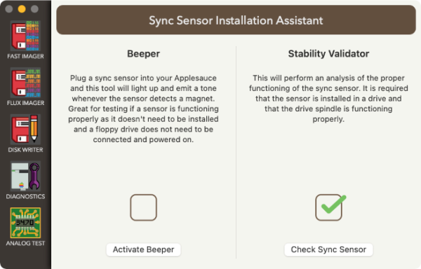
Before you stick the sensor in place, you should test the mounting location. The best way to do this is to connect the sync sensor cable to the sync sensor. Take the other end of the sync sensor cable and plug it into your Applesauce (make sure that the Applesauce USB is unplugged first). Do not connect up the floppy drive! With the cable in, plug in the Applesauce USB and open up the client software. Under the Drive menu, select the Sync Sensor Assistant… item which will show the screen below. Press the Activate Beeper button. Now you can rotate the wheel and a tone will be emitted from your computer whenever the magnet is right above the sensor. Adjust the position/distance of the sensor so that the tone is sounded very reliably. Next move the magnet very slowly across the sensor and ensure that the tone remains solid the entire time. If the tone turns off and then back on in a single pass of the magnet, then it is very likely that the piece of magnet you are using is damaged (this can happen sometimes when cutting it). If all seems to be working well, then turn off the Beeper and get back to reassembling your drive. Don’t forget to unplug the USB before you unplug the sync sensor from you Applesauce.
Once you have found the ideal location for the sync sensor, pull off the backing paper from the adhesive pad and stick it into place. Double check that the sensor is still working well.
Fishing the sync sensor cable through the mechanism
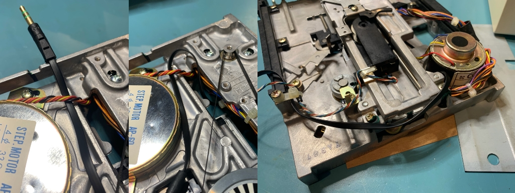
Let’s figure out the best way to get the cable out from under the mechanism. I typically take the sensor to the rear of the mechanism and slide it under the wire as shown below. Then I hook it over the top and go through the hole. This will keep it in place pretty well. Once on the top side of the mechanism, I have it follow the rear of the mechanism to me up with the multicolored twisted wire that it will follow through the analog board.
Install mechanism back into the assembly
Time to start putting things back together. You will need to slide the mechanism back into the assembly rear-first at an angle, just like you took it out. There are a bunch of wires at the rear of the mechanism that you have to ensure that you don’t pinch while putting it back together. Once it is in place, you can put the four screws back that hold the mechanism in the assembly. Now place the shield and insulator back in place, and you want to ensure that you feed the wires through it properly. The big bundle of wires on the right side has a little sleeve around it to protect the wires from being cut by the shielding. The sync sensor and the head wires should be coming through the hole together on the left side of the shielding.
Analog board installation
The analog board can now be put back into place. At the front side, there are a couple of clips that hold the analog board in place. Next install the two screws at the rear of the analog board. After those you can screw the ground step back into place, make sure it is installed in the orientation shown. Now you can reconnect the two cables on the analog board. The head cable on the left side can only be plugged in one way, but the one on the right can be flipped over. Be sure to install the cable in the correct orientation or it will kill your drive when it powers up!
Install assembly back into the case
Screw the main drive cable in place and fish the sync sensor wire out through the same hole. Next install the assembly back into the case. Again you have to so it at an angle and may need some wiggling to make it happen. When the mechanism is nearly in place, be sure to make sure that the LED wire at the front of the case isn’t being pinched. Move it into the correct placement and plug it into the analog board once the assembly is in place.
Reattach shield
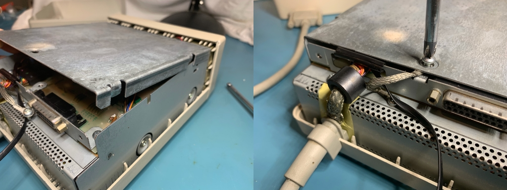
Hook the front of the shield in place and then lower the rear into place. It may take a bit of force to seat it in place. before you close it all the way, be sure to slip the ring of the ground strap under the shield and the screw should go through the hole when you tighten the shield down.
Test the drive and sync sensor
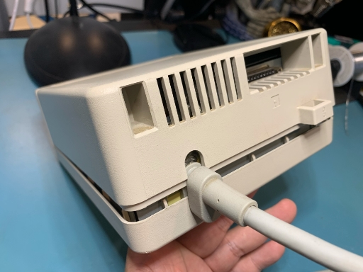
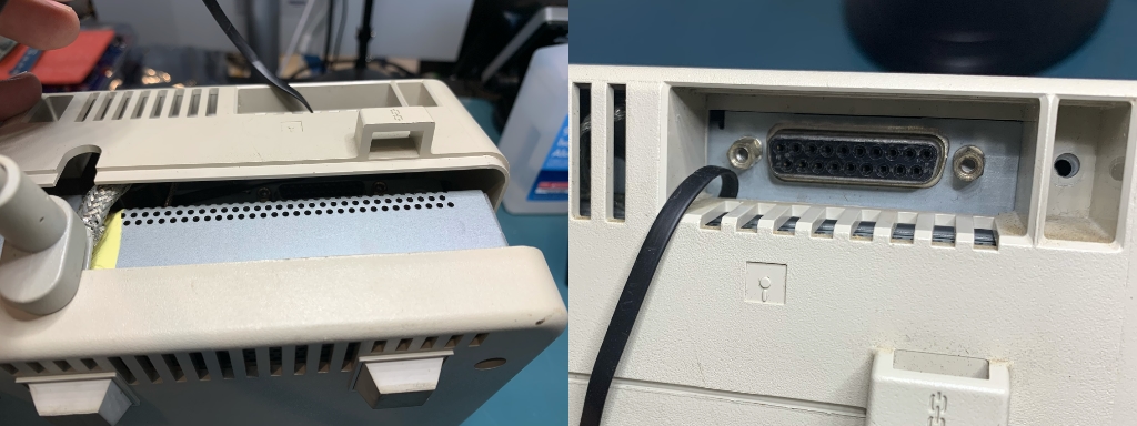
Now it is time to plug your drive and sync sensor into your Applesauce. Go back to the Sync Sensor Assistant and use the Stability Validator to make sure that the installation checks out good. Once everything seems to be working ok, you can finish putting the case back on the drive. You need to fish the sync sensor cable through the daisy chain hole at the rear of the case. You want to be sure the the cable isn’t getting pinched in the case anywhere. If you come in from the bottom face of the hole, there is more room verses the sides which will pinch the sync sensor if you tighten up the screws on the back. Closing up the case can require a bit of wiggling and squeezing in order to get it closed all the way.


